Wednesday, April 16, 2014

Experiment 9 Integrating and Differentiating OP Amps

Introduction: We processed signals through a series of circuits with capacitors, resistors, and OP amps.


Integrating OP amp, Yellow = output Red = input voltage. Note the decrease in amplitude and similar frequencies.  

Saturation. The voltage applied to the OP amp wasn't enough to apply the necessary change, so the output became a square wave with a capacitor-like exponential decay.

Differentiating OP amp, not the increase in amplitude and similar frequency. The phase is noticeably shifted.

Monday, April 14, 2014

Experiment 8: Practical Signal Conditioning


Introduction:
     This experiment requires us to perform level-shifting and scaling processes of an operational amplifier to convert the temperature-proportional voltage in centigrade exiting out of the LM35 into voltage that is proportional to fahrenheit.

Procedure:
   We first start by testing the LM35, applying 9 volts into it relative to ground and seeing what voltage we get as output. Sure enough, we obtained 220 mA, or room temperature.


Now that the LM35 was shown to work, we solved for the output voltage of the op amp circuit according to this diagram.:


We also knew the formula for temperature conversion from celcius to fahrenheit, and we solved for the equation to be in terms of voltage.


Calculation:
Solving for the circuit diagram, we figured the output voltage to be related to the input voltage and the reference voltage by this relation below. Then we solved to find the reference voltage. We also took out resisters from the box that had the correct proportions to our calculated value.

Add caption


Pictures of the experiment:
Materials: 3 variable power supplies (9V, 9V, .4V) , lots of wires, breadboard, LM35 temperature sensor, OP amp, potentiometers...


The complete circuit.


power supplies


Output Voltage:


Error calculation. the .716 mA came from calculation from the value obtained through converting the output of the LM35 voltage into fahrenheit voltage using the celcius-temperature equation.


Conclusion
     The experiment successfully demonstrated the practical uses of an operational amplifier's ability to multiply and add. The conversion had an error of 9.2, which was probably due to the disproportion of the resistors to the actual ratio (18/22 isn't exactly .8) and the uncertainty of the resistors.


Monday, March 31, 2014

Experiment 7: Operational Amplifiers

Introduction:
The purpose of this lab is to condition a signal from a voltage input to a required voltage output.
- Set up voltage divider circuit in order to obtain signal voltage in DC
- Set up Inverting op amp circuit that conditions signal from 0 to 1 v to 0 to -10v
- measure the values
- conclusion

Procedure:
We first consider the entire circuit and determine the necessary resistors
-The sensor may only output a maximum of 1mA of current.

V_cc = 12 V.
V_ee = -12 V. 
V_in = 0 V to +1 V.
V_out = 0 V to -10 V.


We then create a voltage dividing circuit that will condition the input voltage to the specifications of the signal.
R_y = 909 Ohm


potential drop for R_y should now be 1 volt. the pot may be decreased at any point to reduce the voltage.

To be sure, we would like to calculate to make sure R_x will not be over its power limit (1/4 watts).

The minimum resistance that would prevent unnecessary overpowering for R_x is 1152 Ohms, but we will use 1300 ohms as the bare minimum to be safer.


If we were to use the 1300 Ohm resistor, we calculated the value of R_y needed for the potential drop to be 1V.

R_y = 118 Ohm


But the low resistance might condition the OP amp to unappreciably "load" the divider ciruit, so we will use a 10k Ohm R_x value.


These values are what we used for our model.


By decreasing the value of the POT to a value lower than 909, we were able to obtain necessary voltages for the signal input.

Our Circuit and stuff.


More Pictures of the circuit and stuff


The results.


Conclusion:
     The results conclude that there was a gain of -10 through the OP amp, which conditioned the signal to the desired voltage. The current was never over 1 milliamp, and the voltage divider resistor did not burn. The experiment was a success.


Monday, March 24, 2014

Experiment 5: Thevenin Equivalents

Introduction:
     Thevenin Equivalents help us to model linear circuits as a single resistor and power supply. We performed an experiment that proves the validity of Thevenin equivalent circuits.
Objective:
     Test a complicated circuit and measure voltage and current readings through a load, then replace with the thevenin equivalent circuit and measure the voltage and current readings Analyze and interpret the data and perform any error analysis if necessary.

Procedure:
   
This is our original circuit diagram We decided to perform some calculations to find thevenin voltage and resistance.

V1 = V2 = 9V ; Cable 1 (C1) = 100 Ohm ; Cable 2 ((C2) = 39 Ohm ; Cable 3 (C3) = 39 Ohm ; Load 1 (L1) = 680 Ohm ; Potential drop across Load 2 = 8V


Thevenin Voltage = 


Thevenin Resistance / Norton Current

Now that we figured out our thevenin voltage and current, we consider multiple situations for the thevenin circuit.

Required resistance for a potential drop of 8 volts (minimum resistance)


Current through the thevenin equivalent circuit with no load.


Potential drop through load with infinite resistance.


Our Resistors


Setup with resistor boxes


Resistor box and power supply measurements for the thevenin equivalent, theoretical vs actual


Measured voltage vs Theoretical Voltage through the Potentiometer


The results seem to match our predictions on paper within reasonable uncertainty taking into account the differences in our theoretical to actual measurements.

We use the same materials, but with more wires and other necessities for the unthevinized circuit.


Resistor and voltage measurements for our un-thevinized circuit.


The results


The potential drop through the load and also the current matches with our thevenin circuit.


Finally, we will verify that the power supplied is maximized by the formula P = Vth^2/4Rth


Conclusion: The thevenin equivalent allows us to lessen our troubles in calculation when we plug things into a linear ciruit.

Monday, March 17, 2014

Experiment 4: "Transistor Switching"

Introduction

a/b. Use the transistor to switch on and off an LED light, then use your finger.

c. Use a POT to regulate resistance to change the current.

d. Follow up questions.


Procedure

a. Experiment 1: 

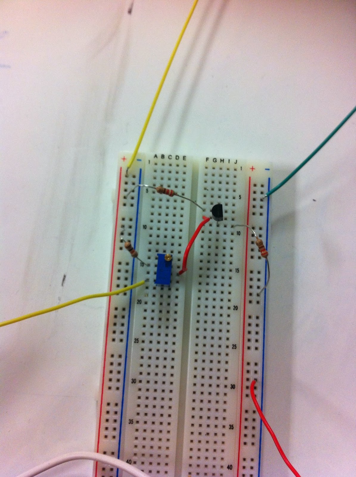
The equptments

First Experiment


b. Experiment 2:


The Setup


c. Experiment 3:
Exp 3 circuit

Initial Setup

Experiment and data collection


d. Follow up question:


The Beta gain should be 2.4253.


Sunday, March 16, 2014

Experiment 3: "Nodal Analysis"

Introduction
     Perform nodal analysis on a reliable power system.
PART A
     - Find the nodal voltage of point 2 and 3
     - Find the current through battery 1 and 2
     - Calculate power supplied by each battery
     -Perform an experiment to verify the results.
     -Analyze the theoretical with the measured results.
PART B
     - Find the nodal voltages of each node such that the middle two nodes are of equal potential.
     - Find the current through battery 1 and 2
     - Calculate power supplied by each battery
     -Perform an experiment to verify the results.
     -Analyze the theoretical with the measured results.

Procedure

PART A

     This circuit was set up and we calculated the nodal voltage of point 2 and point 3, which turned out to be 10.28V and 8.67V.


We then calculated the current and power associated with the batteries


Our Circuit was set up based on the diagram. Because we used variable box resistors, building the circuit was more complex.


We measured each of the circuit elements taking note of the differences from our theoretical values.


Here is our results.


The measured results were off by a large margin, which was possibly due to the inaccuracy of the meters. It is difficult to measure small currents.

PART B

     The circuit was set up such that point 2 and point three were 9 volts.
The power supply was found to be: and the current also to be:


Power is calculated by this:


We used a variable power supply for this part.


Our measured Voltages and currents were very similar to our predictions.


Conclusion

     Part A: The result wasn't as expected. There were large errors that have to be accounted for, and the measured value of the resistors and voltages compared to the theoretical values aren't the culprit. I believe the power supply was somewhat current dependent or that the current meter couldn't handle precision to the milliamps.

     Part B: When hooked to the variable power supply, the currents and voltages were within the uncertainty of +- 5%, which meant that the circuit was hooked correctly and our theoretical calculations matched our measured values.